by Jerry Petersen, Lauderdale Lakes
Work on Swingin Shepherd, my 24 foot 1954 Shepherd hardtop, continues. One task in my renovation project has been the conversion of the hydraulic shifter to a mechanical one. Shepherd, not to be out done by ChrisCraft with its Chris-O-Matic, installed hydraulic shifters on many of their engines. My Chrysler Hemi has a separate gear driven oil pump that draws oil from the crankcase and directs it at 65 psig through a three way valve on top of the transmission. 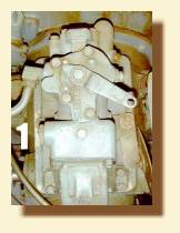 Figure 1, shows this valve with the control linkage removed. Depending on the valve position, the high pressure oil is directed to either end , or to the center, of a piston that is linked to the gear box shifting mechanism. The valve position, in turn, is controlled by a stick on the right hand side of the steering column. It all looks pretty slick, but it is not without a couple of big downsides.
In September, 2000, I used my newly acquired boat on the Michigan Lake Hop before the Annual ACBS Meeting on Mackinaw Island. I soon found the hydraulic shifter to have two problems. First, it takes 3 full seconds to shift, and second, you cant partially engage the prop to position the boat during docking. Losing the partial engagement feature was especially frustrating during docking on a boat lift, or on my trailer, in a side wind. I also found shift control to be more critical on this boat than on my smaller GarWoods. This follows from its larger profile, which acts as a sail in the wind, and having only one engine to work with when docking. Hence, I made the decision to convert the gear box to a conventional mechanical shift, with the classic stick at the helm.
I found it fairly easy to unhook the linkage from the hydraulic cylinder to the gear train, and fortunately, the gear box did have the normal side shaft to which a mechanical shifter lever could be attached. I was able to find a gear box lever with the proper shaft diameter, but I had to have a welder lengthen it so that the shaft attachment would be below the cockpit floor. 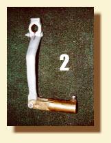 Figure 2 shows the lengthened gear box lever with the pipe fitting attached. I also found a classic helm shift lever, and the half inch pipe thread brass connector required. I had the helm lever re-plated and it looks great. Figure 3 shows the re-plated helm shift lever with its brass pipe connector attached.
My next challenge was the shift direction. Since my engine is configured as a V Drive, the shift directions are reversed. That is, the gear box shift lever has to be pulled forward to go forward, rather than pushed back. I verified this by cranking the engine with the transmission in gear. This means that I had to reverse the pivot point on the helm lever if I wanted to 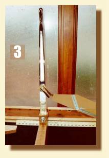 go forward when I pushed it forward. Normally, the lever pivots just below the floor, and the pipe attaches to the bottom. I had to reverse these connections. I also needed to lengthen the throw to compensate for the longer lever on the gear box. To accomplish this I bolted two strips of 3/8 inch brass plate to the lower end of the shift lever, and drilled a ½ inch hole through both plates near their lower end to engage a ½ inch stainless steel pivot bolt.
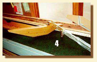 I also had to cut off the original pivot boss on the side of the lever to permit attachment of the front pipe connector just below the floor level. Figure 4 shows this arrangement.
Next, I had to determine just where the front shift lever should be placed in the boat. Of course, it must be readily accessible at the helm, but care had to be taken to be sure full throw could be obtained without interference with the front seat, or with the front bulkhead.
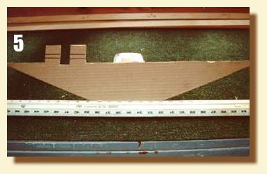 I determined that this meant the pivot point had to be just in front of the frame forward of the front seat. I decided to make a pivot fixture out of eight quarter white oak. Figure 5 shows the cardboard pattern for this fixture.
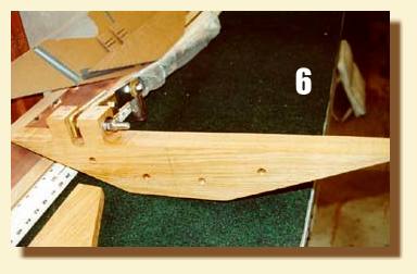 Figure 6 shows the cut white oak fixture, before sealing with CPES, but with the shift lever temporally attached
Unfortunately, I had to cut through the upper cross member of the frame to which the helm shift lever would be attached to permit the long swing of the lever. Hence, I also decided to make a four quarter white oak brace to strengthen this frame.
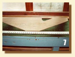 The added brace attaches to the back of this frame and to the bottom of the upper cross frame member that had to be cut. Figure 7 shows this brace. The cut out at the top provides space for control cables to pass. I secured everything by bolting through the pivot fixture, the frame, and the brace using four 3/8 inch brass bolts.
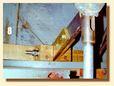 The brace is also secured with 5200 to the frame, and by long #12 silicon brass screws and 5200 to the cut upper frame cross member. Figure 8 shows this final assembly.
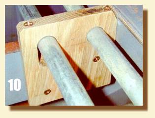
The one remaining task was to make new pipe guides. The boat originally had three single pipe guides for the rudder pipe. I removed these guides and made new guides with holes for both the rudder and gear shift pipes out of three quarter white oak. This task was fairly straight forward, but each guide had different hole spacing, and the forward one required a vertical slot for the shift pipe. This slot accommodates the vertical pipe movement of about an inch as the forward lever rotations to achieve 7 ½ inches of lateral pipe movement. I also decided to split the guides, so they could be installed without removing the pipes. This did necessitate cutting and fastening them before drilling the large holes with a Forstner bit. 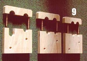 Figure 9 shows the three guides on my bench, and Figure 10 shows the forward guide temporally installed before sealing with CPES. As an aside, I was surprised how difficult it is these days to find 21 foot sections of ½ inch galvanized pipe. Copper and plastic are all most plumbers currently use, and home centers carry only 10 foot lengths of galvanized, when they do carry it. On about my tenth try, I found a large plumbing firm in Milwaukee that had the long piece I needed.
 With the shifter task done, Im returning to wood working, re-wiring and re-finishing. I have replaced ten side planks, twelve knees, parts of both chines, and of course all the transom frames as described in previous BOATHOUSE articles. I will not make, and install, the new transom planks until all the wiring is done. Its so much easier to access the engine compartment with them off. I do have a nibble on my WANTED AD for windshield wipers, and hope to get a pair at Mt. Dora in March. I know this was a Shepherd option, but unfortunately my boat wasnt ordered with them. Since it is almost impossible to reach the windshield from the helm, I think they will be sorely needed in rainy weather. My biggest remaining task is refinishing, including cutting and installing new interior covering boards and floor boards. One new addition will be a forward scanning sonar. This boat came with a conventional sonar using vacuum tubes! I have purchased an Interphase unit that scans forward the distance of about ten times the depth, as well as to the side. I hope this will help me stay afloat on river trips. See you all at the 2002 Rendevous, and hopefully at the 2003 Rendevous with the finished Swingin Shepherd..